Hi Peter,
The installation pics look great, nice and tidy install. Regarding the noise, my Paktrakr suffers similar symptoms in my volvo, ie the display freezes intermittently. A while ago I found some info on this from another person with similair problems. He looked at various solutions and in the end found a single 100 ohm resistor cleaned up the signal enough to make the display behave normally. The Paktrakr layout is similar to what you have designed in that it has a number of "slaves" linked together reporting battery voltage and a "master" display that does calculations and gives a display readout. only 3 wires connect to the display, feed, earth and signal wire. The resistor was connected in series in the signal wire near the display. Maybe a similair setup might work for you. Curiously the same Paktrakr doesn't seem to suffer the same problems in my Fiat.
Old BMS General Thread
Moderators: GregsGarage, retepsnikrep
-
GregsGarage
- Posts: 870
- Joined: Tue Apr 01, 2008 5:27 pm
- Location: Galashiels, Scottish Borders
- Contact:
-
mikep_95133
- Posts: 28
- Joined: Thu Sep 25, 2008 6:38 pm
Isn't debug fun? It sure separates the boys from the men, or me from my sanity 
I'll be on vacation starting Monday. That excuse one for not having my BMS installed. #2 is that the second truck has taken all of my time to get corrections made to it's various electrical systems. It's basically done. Just needs a new pack. So the #1 truck is the tough vehicle to get a shielded cable from the pack to the interior of the truck. Once the cable is mounted through the wall of the pack, then adding the BMS is easy. Now I have Thundersky's that I have been testing as well as 3 new 50ah Hi Power cells to test.
To look for noise it's helpful to determine if it's conducted or radiated noise. Steps that I use.
Conducted Emissions
1) I like to use clip on ferrite beads for initial debug. Easier and faster than adding components. The kind you see attached to a wall wart power supply or your pc monitor cable. 25-30mm long. 15-20mm in diameter. When picking them up from surplus locations, get a few different versions as you don't know which RF material they are made from. Clip them onto both ends of the master bus cable. One at the master board and one at the first slave. Check for changes. Does the system work better? Verify with a scope, always.
2) Now repeat step one with the Slave bus, with all of the master bus ferrites removed. The slave bus could easily carry EMI/RFI and cause issues.
3) Repeat step one with ferrites on Master and Slave bus.
4) The shotgun approach is to just do both Master and Slave bus at the same time. But you won't know the sources of noise as well.
If 1-4 improve function then it's the noise is mostly conducted emissions. Although radiated emissions from the vehicle could turn into conducted emissions due to the huge amount of wiring we have to use.
5) Always twist pairs of cables to 4 turns per 25.4mm(1 inch) between slaves. Cordless drill works great for twisting wires together.
6) Use shielded cables with twisted pairs for Master to first slave cables.
Radiated Emissions
Here is a fantastic article on how to make a home made probe for sniffing EMI/RFI with your scope from a piece of coax a tiny ferrite bead, and some sandpaper. When I showed the crew at work this article, everyone had me making these probes for them.
http://www.elecdesign.com/Articles/Inde ... =7491&pg=1
Here is the probe I made from the article.
http://www.rotordesign.com/clone/EMIprobe.jpg
Below are scope shots using my probe on a project that has so much EMI that it smoked the processor and other drivers badly enough that my head with a full face helmet, hit the ground hard and made me unconscious. Had a concussion for a year. So EMI and I have become great friends!
There are EMI and RFI (aka E field) probes. An E field probe is just the ground of your scope probe tied to the probe tip. It shorts it in a dc sense. But for RFI, it's a path to joy and harmony. If you make your probe ground lead a bit longer and coil it, the probe becomes much more sensitive to weak signals.
Both EMI and RFI probing examples of my concussion making machine (a home made self balancing scooter) are shown in this link:
http://www.rotordesign.com/clone/ScopeImages.jpg
These scope shots showed me clearly at the time where the emissions were coming from. Each output from the processor got a 1k resistor to isolate it from the drivers. A 1k resistor was put on the output of the driver chips. These two steps did not reduce EMI, but did reduce it from getting into the sensitive parts. The next step was to reduce the EMI itself. I had used 250mm long ribbon cables for connecting the master board to two slaves (control board to 2 H-bridge boards). Normally the ribbon cables are about 50mm long. Reinstalling the 50mm cables did the trick. The EMI probe showed me the way. As you can see from the scope shots I also found EMI from the power supply inductor as well that I could follow with my handy EMI probe along a ground trace. That's right. EMI was following the ground!!
So assume nothing, and measure everything!!
Mike
-
retepsnikrep

- Posts: 1387
- Joined: Sat May 26, 2007 4:50 pm
- Location: North Yorkshire England
- Contact:
Thanks for all advice. i'm relaxing a bit as now. I'll tinker as time permits.
Another option is to fall back to analogue mode while I'm tinkering, as that would at least let me build up the experience with the lithium cells and get them in and running
Luckily my BMS digital slave boards can be programmed to output a simple on/off over V on the Master bus when a cell goes over Abs Max V, and although not quite as good as analogue slaves for the under V mode they can still pass an under V situation message amongst themselves and out of the last board again as simple on/off signal. Both these signals are opto isolated and could be used to drive a simple dash warning led/audible alarm. The over V signal can also control the charger via a simple relay, as soon as the first cell hits max charge will be cut. I can monitor battery voltage and current with a couple of simple analogue meters. I'm very used to using a simple voltage meter as a fuel gauge from my years of driving with Li-ion and pb in my EV's!
I know it's not ideal but it gets it up and running with fairly minimal effort and I might be able to manage that over the holidays. We will also find out about how far the Insight will go with the extra charge and how it interacts with the bcm in more detail. All useful stuff. The Master is the icing on the cake and can come on stream as things progress with screening/filtering etc.
Regards Peter
Two MK1 Honda Insight's. One running 20ah A123 Lithium pack. One 8ah BetterBattery Nimh pack.
One HCH1 Civic Hybrid running 60ah A123 Lithium pack.
Two MK1 Honda Insight's. One running 20ah A123 Lithium pack. One 8ah BetterBattery Nimh pack.
One HCH1 Civic Hybrid running 60ah A123 Lithium pack.
-
retepsnikrep
- Posts: 1387
- Joined: Sat May 26, 2007 4:50 pm
- Location: North Yorkshire England
- Contact:
Just amended software for my 50 digital slave boards to allow them to operate in analogue mode.
www.solarvan.co.uk/bms/ANALOGUESLAVE_DI ... 08_V01.TXT
They basically now just output a simple high or low signal on the Master & Slave buses when a cell goes over or under permitted voltages.
The Master bus (High V) is paralleled and is easy, but the Slave Bus (Low V) signal is cascaded through the chips.
Sorry to Greg who built his slaves in Analogue configuration you could perhaps have built them in digital config and just used this software for the analogue control. It only needs the addition of one final opto on the last Slaves output
  Oh well live and learn.
I'll use this to allow the install to proceed with a simple visual/audible alarm. The Master bus which has become the Over V bus can also be still used to control a simple relay to control the mains charger, I can do a manual balancing charge if I need to when I see how well the cells keep in balance whilst I'm using this analogue functionality. The slave boards still retain their on board 250ma balancing load capability and 10x voltage over sampling, I'll run them at the standard 4mhz. I'll just add an analogue voltmeter to allow me to monitor the pack voltage and I'll try the install again.
www.solarvan.co.uk/bms/ANALOGUESLAVE_DI ... 08_V01.TXT
They basically now just output a simple high or low signal on the Master & Slave buses when a cell goes over or under permitted voltages.
The Master bus (High V) is paralleled and is easy, but the Slave Bus (Low V) signal is cascaded through the chips.
Sorry to Greg who built his slaves in Analogue configuration
I'll use this to allow the install to proceed with a simple visual/audible alarm. The Master bus which has become the Over V bus can also be still used to control a simple relay to control the mains charger, I can do a manual balancing charge if I need to when I see how well the cells keep in balance whilst I'm using this analogue functionality. The slave boards still retain their on board 250ma balancing load capability and 10x voltage over sampling, I'll run them at the standard 4mhz. I'll just add an analogue voltmeter to allow me to monitor the pack voltage and I'll try the install again.
Regards Peter
Two MK1 Honda Insight's. One running 20ah A123 Lithium pack. One 8ah BetterBattery Nimh pack.
One HCH1 Civic Hybrid running 60ah A123 Lithium pack.
Two MK1 Honda Insight's. One running 20ah A123 Lithium pack. One 8ah BetterBattery Nimh pack.
One HCH1 Civic Hybrid running 60ah A123 Lithium pack.
-
GregsGarage
- Posts: 870
- Joined: Tue Apr 01, 2008 5:27 pm
- Location: Galashiels, Scottish Borders
- Contact:
Peter,
That's a clever idea of using the digital slave in both analogue and digital mode. I'm not too upset because mine have been working well for some months now, improvements are inevitable. I have also been thinking about how you are controlling the charger with a simple on/off control. My module could use an output to drive a opto connected to the charger when it sees a high voltage signal. It can try and lower the voltage and if after a certain time the high voltage warning is still there then it will switch off the charger as it does now. Will have to take my charger apart and see if I can find the voltage trim pots.
I have uploaded the latest version of my software here; http://www.batteryvehiclesociety.org.uk/forums/viewtopic.php?t=1442
I have been using this since early September and so far no problems. The boards are designed for industrial use so should be able to withstand a fair amount of noise/interference.
That's a clever idea of using the digital slave in both analogue and digital mode. I'm not too upset because mine have been working well for some months now, improvements are inevitable.
I have uploaded the latest version of my software here; http://www.batteryvehiclesociety.org.uk/forums/viewtopic.php?t=1442
I have been using this since early September and so far no problems. The boards are designed for industrial use so should be able to withstand a fair amount of noise/interference.
Greg Fordyce
Daewoo Matiz
http://www.evalbum.com/4191
Daewoo Matiz
http://www.evalbum.com/4191
-
retepsnikrep
- Posts: 1387
- Joined: Sat May 26, 2007 4:50 pm
- Location: North Yorkshire England
- Contact:
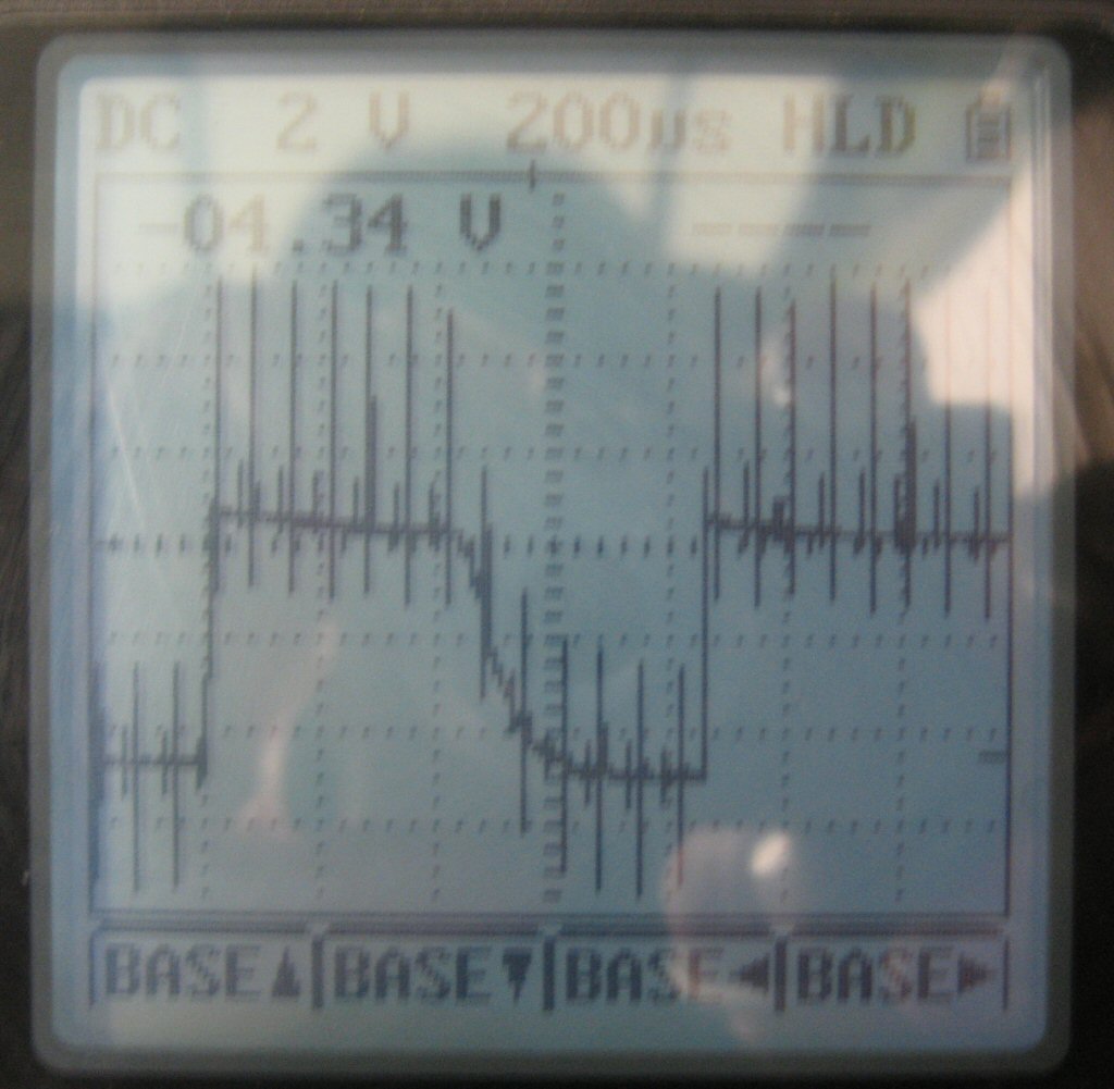
Looking at the spikes in my scope pic earlier anyone good at maths want to give me a few values for the low pass RC filter components. I know the formulae but it's all double dutch equations to me.
http://www.solarvan.co.uk/bms/Noise1912.jpg
You can see the scales for the display.
2v per divison vertical
200us per division horizontal
The spikes are very clear and very short prob <50us , the underlying serial data pulse is about 500us long.
http://www.solarvan.co.uk/bms/Noise1912.jpg
You can see the scales for the display.
2v per divison vertical
200us per division horizontal
The spikes are very clear and very short prob <50us , the underlying serial data pulse is about 500us long.
Regards Peter
Two MK1 Honda Insight's. One running 20ah A123 Lithium pack. One 8ah BetterBattery Nimh pack.
One HCH1 Civic Hybrid running 60ah A123 Lithium pack.
Two MK1 Honda Insight's. One running 20ah A123 Lithium pack. One 8ah BetterBattery Nimh pack.
One HCH1 Civic Hybrid running 60ah A123 Lithium pack.
If you take 1k resistor as a R then you should try capacitor of something like 10-22nF.
I've done some simulation VSM circuit for you so you can experiment with values: http://www.sklandymas.lt/EV/RC_noise_filter.DSN
The simulated scope shows how your filtered output should look like if you put a 22nF C3 filter capacitor: http://www.sklandymas.lt/EV/RC_noise_filter.png
Please note that we don't know your data line output's impedance. Basically you should add this impedance to RC filter resistor R3 value when simulating.
http://hr-ev.blogspot.com
-
retepsnikrep
- Posts: 1387
- Joined: Sat May 26, 2007 4:50 pm
- Location: North Yorkshire England
- Contact:
-
retepsnikrep
- Posts: 1387
- Joined: Sat May 26, 2007 4:50 pm
- Location: North Yorkshire England
- Contact:
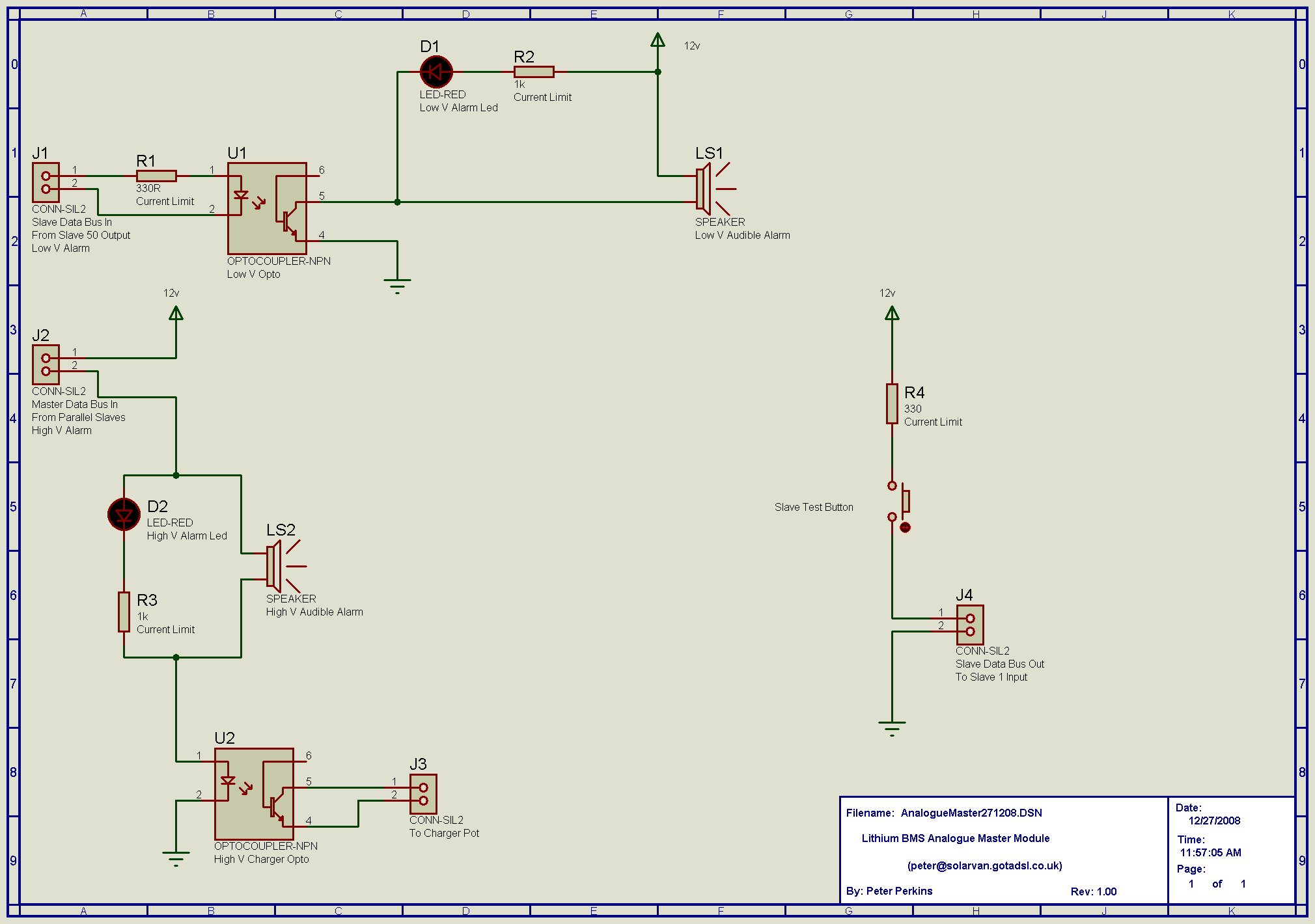
I've knocked up a simple analogue Master circuit to provide visual and audible Over - Under Voltage indication and charger control. I intend to install this this week to allow me to actually test cells in situ and see how it reacts with the Insight BCM etc. I'll add a simple 0-200v voltmeter as well as a simple fuel gauge 
www.solarvan.co.uk/bms/AnalogueMaster271208.jpg
While I'm doing this testing I shall move and adapt the Digital Master with some re-wiring, filtering.
I'm moving it out out of the IPU compartment which is an rf nightmare, and am going to put it behind the now redundant battery cooling air vent behind the drivers seat with some rear aluminum screening.
I can then get at it by simply prising out vent grille, at the moment I have to go into rear compartment and disconnect far too much stuff
As it's out of the rf area it should be better for it as well.
I have found it is critical to ensure cells/pack can accept the first forced charge and are not full on first install. I would say charged to about 75% max is enough. The forced charge rate was about 6A for about 3-4 minutes until BCM had enough data to give an initial SOC.
The IMA then operated normally.
When I re-installed the nimh pack it did the initial soc forced charge, and then did a positive recal after that within about five miles, increasing soc to one bar from top. (That had been the indicated soc of the pack when I took it out)
I didn't run the lithium pack past the forced charge stage during my initial testing, so it will be interesting to see if it also does a positive recal as well when I put it back in, as it had a higher open circuit voltage than the nimh pack.
Hope to do this work within next week as I have a few days off.
www.solarvan.co.uk/bms/AnalogueMaster271208.jpg
While I'm doing this testing I shall move and adapt the Digital Master with some re-wiring, filtering.
I'm moving it out out of the IPU compartment which is an rf nightmare,
I can then get at it by simply prising out vent grille, at the moment I have to go into rear compartment and disconnect far too much stuff
As it's out of the rf area it should be better for it as well.
I have found it is critical to ensure cells/pack can accept the first forced charge and are not full on first install. I would say charged to about 75% max is enough. The forced charge rate was about 6A for about 3-4 minutes until BCM had enough data to give an initial SOC.
The IMA then operated normally.
When I re-installed the nimh pack it did the initial soc forced charge, and then did a positive recal after that within about five miles, increasing soc to one bar from top. (That had been the indicated soc of the pack when I took it out)
I didn't run the lithium pack past the forced charge stage during my initial testing, so it will be interesting to see if it also does a positive recal as well when I put it back in, as it had a higher open circuit voltage than the nimh pack.
Hope to do this work within next week as I have a few days off.
Regards Peter
Two MK1 Honda Insight's. One running 20ah A123 Lithium pack. One 8ah BetterBattery Nimh pack.
One HCH1 Civic Hybrid running 60ah A123 Lithium pack.
Two MK1 Honda Insight's. One running 20ah A123 Lithium pack. One 8ah BetterBattery Nimh pack.
One HCH1 Civic Hybrid running 60ah A123 Lithium pack.
-
Teslas fag packet

- Posts: 153
- Joined: Thu Aug 16, 2007 7:35 pm
- Location: Leeds
- Contact:
Well thank god just when you have given up all hope a fantastic project such as this comes along
Peter and Greg nice work, I like the use of the SV2000 chip, crafty like it.
I calculate the noise to be 25Khz from what I can see, this seams a very deliberate frequency if you know what I mean, RFI from the charger/inverter I would guess.
I doubt this is a termination issue.
What I will say is if it were me I would have current down the optos (LEDs) all the time and short them out with an open collector NPN to send data (at the other end), this would be like a poor man current mode of sending data, and this would be much better on the susceptibility front.
Let me know what you think
Ta
Tes
Who is online
Users browsing this forum: No registered users and 62 guests