10kW BLDC outrunner drive
Posted: Sun Nov 23, 2008 8:19 pm
So far just plans... I think Jeremy's multi-motor approach is just the thing for a big "secret project" I've started on, but we'll need special electronic drives.
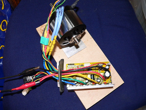
Current plan is to make "drive modules" with 4x 2.5kW outrunner motors on a single shaft - so I'll need a 40V 300A converter for each module.
I intend to use slotted opto switches to control the commutation process & have a separate "buck" converter driven by a current mode SMPS controller to control its DC link. I hope that by separating the control and commutation tasks, and by not attempting sensorless (BEMF) control, I will end up with a task that is POSSIBLE at home in a reasonable timeframe. Furthermore the "current mode" switcher will limit any fault currents & make my power stage more likely to survive the development process...
Development steps are:
1) make a single motor drive & dynamometer test bench using an induction motor & inverter. This will be tried in a 36V battery training vehicle by our greenpower team.
sub tasks: a) make a little 5A inverter running from bench supply in current limit, spin motor, resolve position feedback sensitivity & accuracy issues: b) make the front end converter (synchronous buck, current mode): c) beef it all up
2) Extend to 4 motors on a longer shaft & 10kW
3) combine several modules onto a single driveshaft using a special reducing combining gearbox.
I'll try to keep the forum up to date on progress as it happens. I'll open a flickr account for the pictures I guess - my free web-space from my ISP is pretty full now!
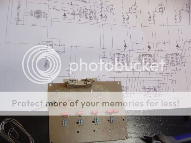
Progress to date: 1st PCB (with the slotted switched) now being produced
Current plan is to make "drive modules" with 4x 2.5kW outrunner motors on a single shaft - so I'll need a 40V 300A converter for each module.
I intend to use slotted opto switches to control the commutation process & have a separate "buck" converter driven by a current mode SMPS controller to control its DC link. I hope that by separating the control and commutation tasks, and by not attempting sensorless (BEMF) control, I will end up with a task that is POSSIBLE at home in a reasonable timeframe. Furthermore the "current mode" switcher will limit any fault currents & make my power stage more likely to survive the development process...
Development steps are:
1) make a single motor drive & dynamometer test bench using an induction motor & inverter. This will be tried in a 36V battery training vehicle by our greenpower team.
sub tasks: a) make a little 5A inverter running from bench supply in current limit, spin motor, resolve position feedback sensitivity & accuracy issues: b) make the front end converter (synchronous buck, current mode): c) beef it all up
2) Extend to 4 motors on a longer shaft & 10kW
3) combine several modules onto a single driveshaft using a special reducing combining gearbox.
I'll try to keep the forum up to date on progress as it happens. I'll open a flickr account for the pictures I guess - my free web-space from my ISP is pretty full now!
Progress to date: 1st PCB (with the slotted switched) now being produced